Injection mould tool design determines how a plastic component is formed, how consistently it meets specification and what it costs to manufacture. A mould tool must produce the required geometry, control cooling and release the finished component without damage. Decisions about tooling materials, cavity numbers and component design affect the initial investment, production cycle times and long-term manufacturing costs.
What the tool has to do
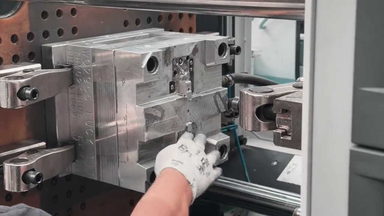
An injection mould tool is a precision-machined metal assembly used to form molten plastic into a finished component. Most tools consist of two halves containing a cavity and core. When the tool closes, these create the space into which molten plastic is injected. The plastic cools and solidifies before the tool opens and the component is ejected.
The tool determines the component’s geometry, surface characteristics and many of its dimensional features. It also incorporates systems for material flow, cooling and ejection. A tool can contain one cavity or several, allowing multiple components to be manufactured during each cycle. Gemini’s injection mould tooling services support the manufacture of plastic components to customer specifications.
The parts of an injection mould tool
Injection moulding tooling design involves several components working together. Some form the plastic part, while others control material flow, temperature, alignment and ejection.
| Component | What it does | Why it matters |
|---|---|---|
| Cavity | Forms the external surfaces of the component. | Determines external geometry and surface finish. |
| Core | Forms internal surfaces and features. | Controls internal dimensions and geometry. |
| Sprue bush | Provides an entry point for molten plastic. | Connects the injection nozzle to the feed system. |
| Runners | Carry molten plastic towards the cavities. | Influence material distribution and waste. |
| Gate | Controls where plastic enters the cavity. | Position affects filling and visible gate marks. |
| Cooling channels | Circulate coolant through the tool. | Influence cycle time and dimensional stability. |
| Ejector pins and plate | Push the component out after cooling. | Pin positions can leave visible marks. |
| Guide pins and bushes | Align the tool halves during closing. | Help maintain alignment and prevent flash. |
| Parting line | Defines where the tool halves meet. | Can leave a visible line on the component. |
| Vents | Allow displaced air to escape. | Help prevent incomplete filling and burn marks. |
| Slides and lifters | Form features that prevent straight ejection. | Add mechanical complexity and maintenance requirements. |
| Back plates and bolsters | Support and secure the tool assembly. | Provide structural support and mounting. |
Not every tool requires every component. A straightforward housing may need a simple core and cavity arrangement, while components with side openings or internal undercuts can require additional moving mechanisms.
How the tool is made
Injection mould tool making typically begins with a detailed tooling design developed from the component’s CAD model. CNC machining is commonly used to produce the core, cavity and supporting components. Electrical discharge machining (EDM) may be used for intricate features that are difficult to produce with conventional cutting tools. The individual components are then finished, assembled and checked before the completed tool undergoes its initial trials.
Tool materials: soft tooling and hard tooling
Tool material selection affects manufacturing cost, lead time, wear resistance and expected working life. The appropriate choice depends on production quantities, component complexity and the plastic being processed.
When aluminium suits
Aluminium is generally faster to machine than tooling steel, which can reduce initial manufacturing costs and lead times. Often described as soft tooling or rapid tooling, aluminium moulds are used for prototypes, bridge production and lower-volume manufacturing. Aluminium also conducts heat efficiently, although cooling performance depends on the overall tool design.
Its main limitation is lower wear resistance compared with suitable tooling steels, particularly when processing abrasive materials. For appropriate applications, aluminium can provide an economical route to low-volume injection moulding.
When P20 steel suits
P20 is a pre-hardened tool steel commonly used in plastic injection mould manufacture. It provides a balance of machinability, strength and wear resistance, making it suitable for many production applications. Compared with aluminium, P20 generally requires a greater initial investment but offers improved durability. Its expected working life depends on the plastic material, tool construction and operating conditions.
When hardened steel is needed
Hardened tool steels are used where additional wear resistance is required, particularly for extended production runs or abrasive materials such as glass-filled polymers. These materials generally require more demanding machining and processing, increasing the initial tooling investment.
Tool material comparison
| Tool material | Typical lead time | Guaranteed tool life | Suitable production volumes |
|---|---|---|---|
| Aluminium | Four to six weeks | Up to 10,000 parts | Prototypes, bridge production and lower volumes |
| P20 steel | Six to eight weeks | Into the hundreds of thousands of parts | Higher-volume production |
The guarantee applies while Gemini runs the tool, as explained under tool ownership and maintenance below.
Design decisions that affect tooling cost and lead time
The cost of injection moulding tool design is influenced by the component’s geometry, material requirements and the manufacturing work needed to produce the tool. Several decisions can be reviewed before machining begins.
Single cavity mould vs multi cavity mould
A single cavity mould produces one component per cycle. A multi cavity mould produces several. Family moulds can also produce different components, provided their material flow and processing requirements are compatible. Additional cavities increase tooling complexity and initial manufacturing costs but can reduce the production cost per component by increasing output.
The appropriate arrangement depends on expected annual quantities and production requirements. Providing realistic volume forecasts helps determine whether additional cavities justify the investment.
Undercuts, slides and lifters
Undercuts are features that prevent a component from being released through the tool’s normal opening movement. Side openings, retaining clips and certain internal features may require slides or lifters, increasing tooling complexity and introducing additional moving components.
Small changes to component geometry can sometimes eliminate these mechanisms. Design for manufacture can identify opportunities to simplify the tool before manufacture begins.
Draft angles and component release
Draft is a slight taper applied to component surfaces to help them release from the mould. Insufficient draft can cause components to grip the tool during ejection, potentially resulting in surface damage or deformation.
The required angle depends on the material, component geometry and surface texture. Including appropriate draft in the original component design can avoid costly tooling modifications later.
Cooling system design
Cooling affects component quality and manufacturing cycle time. Uneven cooling can contribute to differential shrinkage, distortion and dimensional variation.
Thick sections generally cool more slowly, while significant variations in wall thickness can produce uneven shrinkage. Maintaining consistent wall thickness wherever practical helps reduce these risks.
Gate positioning
The gate controls where molten plastic enters the mould cavity. Its position influences how the cavity fills and where a gate mark appears on the finished component.
Poor gate positioning can contribute to filling problems or unwanted marks on visible surfaces. For cosmetic components, identifying acceptable gate locations before tooling begins can prevent unnecessary modifications.
Surface finish and texture
Surface finish requirements influence the machining and finishing operations needed to manufacture a tool. Polished surfaces may require additional finishing, while textured surfaces can involve specialist treatment and additional draft requirements. Specify cosmetic requirements early and distinguish visible surfaces from areas where a standard finish is acceptable.
Dimensional tolerances
Tolerances define the permitted variation from dimensions specified on a component drawing. Tighter tolerances can require more precise machining, additional inspection and closer control of moulding conditions. Material shrinkage, geometry and cooling also influence dimensional accuracy. Identify critical dimensions and avoid unnecessarily restrictive tolerances elsewhere.
Selecting the polymer before tooling
The intended plastic material should be established before the tooling design is approved. Different polymers have different shrinkage, flow and processing characteristics, which influence cavity dimensions, gating and cooling requirements.
Changing materials after tool manufacture has begun may require modifications to accommodate these differences. Confirming the intended polymer grade early helps reduce the risk of additional tooling work. These decisions also affect the economics of the subsequent injection moulding process.
Tool trialling and sign-off
Once a mould tool has been manufactured and assembled, it must be trialled before production approval. During initial trials, samples are produced using the intended material and assessed against the component drawing.
Inspection may identify dimensional differences, cosmetic defects or filling problems requiring adjustments to the tool or processing conditions. Further trials establish whether the changes have produced acceptable results. Trial iterations are a normal part of developing a production-ready mould tool.
Gemini trials each new tool and measures the parts to check they are correct. How a customer then validates the tool depends on the application. Many customers check fit and function only. Others need every dimension on the drawing confirmed, and Gemini can supply an ISIR (initial sample inspection report).
Some customers ask for a full PPAP (production part approval process). It validates the material, the process, the tool and the component, with a full inspection report on a minimum number of parts and an analysis of where each dimension sits within its tolerance band. Where a dimension cannot be achieved, Gemini can apply for a concession. Once the customer has the report and the samples, they sign off the tool.
Tool ownership and maintenance
Tool ownership should be agreed before manufacture begins, particularly when the customer funds the initial tooling investment. The agreement should establish ownership, storage arrangements and the conditions under which a tool can be transferred.
When customers manufacture their components with Gemini Manufacturing, Gemini covers the cost of maintaining and replacing the mould tool during ongoing production. This means customers do not need to budget separately for routine tooling maintenance or replacement arising from normal production use. It is an important consideration when comparing the long-term costs of different manufacturing arrangements.
The customer owns the tool. While Gemini runs it, Gemini stores the tool free of charge and covers repairs, wear and any damage, so the tool stays in good working order.
If a customer moves the tool to another supplier, the guarantee ends as soon as the tool leaves Gemini’s facility, because Gemini cannot control how it is run elsewhere. Before a tool leaves, Gemini removes its electrical connectors but leaves the wiring in place, so the new supplier fits and certifies its own connectors.
Frequently asked questions
How long does it take to make an injection mould tool?
Gemini's typical lead times are four to six weeks for an aluminium tool and six to eight weeks for a P20 steel tool. The manufacturing programme depends on tool material, component complexity, cavity numbers and additional mechanisms.
How much does an injection mould tool cost?
The cost is determined by component geometry, tool material, cavity numbers, tolerances and manufacturing requirements. Gemini does not publish a typical price, because tooling costs vary widely from one part to another and material prices, including aluminium, have risen sharply recently. Send a drawing or CAD file for a quotation.
Who owns the mould tool?
The customer owns the tool. While Gemini runs it, the tool is stored free of charge and Gemini covers maintenance and replacement costs. If the tool moves to another supplier, the guarantee ends when it leaves Gemini.
How often does a tool need maintenance?
Maintenance requirements depend on tool construction, processed materials and production cycles. Regular inspection, cleaning and attention to worn components help maintain consistent performance. Gemini covers tooling maintenance costs for customers manufacturing with the company.
Discuss your tooling requirements with Gemini
If you have a component ready for manufacture, provide Gemini with your technical drawing or CAD file, expected annual quantities, material requirements, critical tolerances and surface finish specifications. These details allow the team to assess the tooling requirements and prepare a quotation.