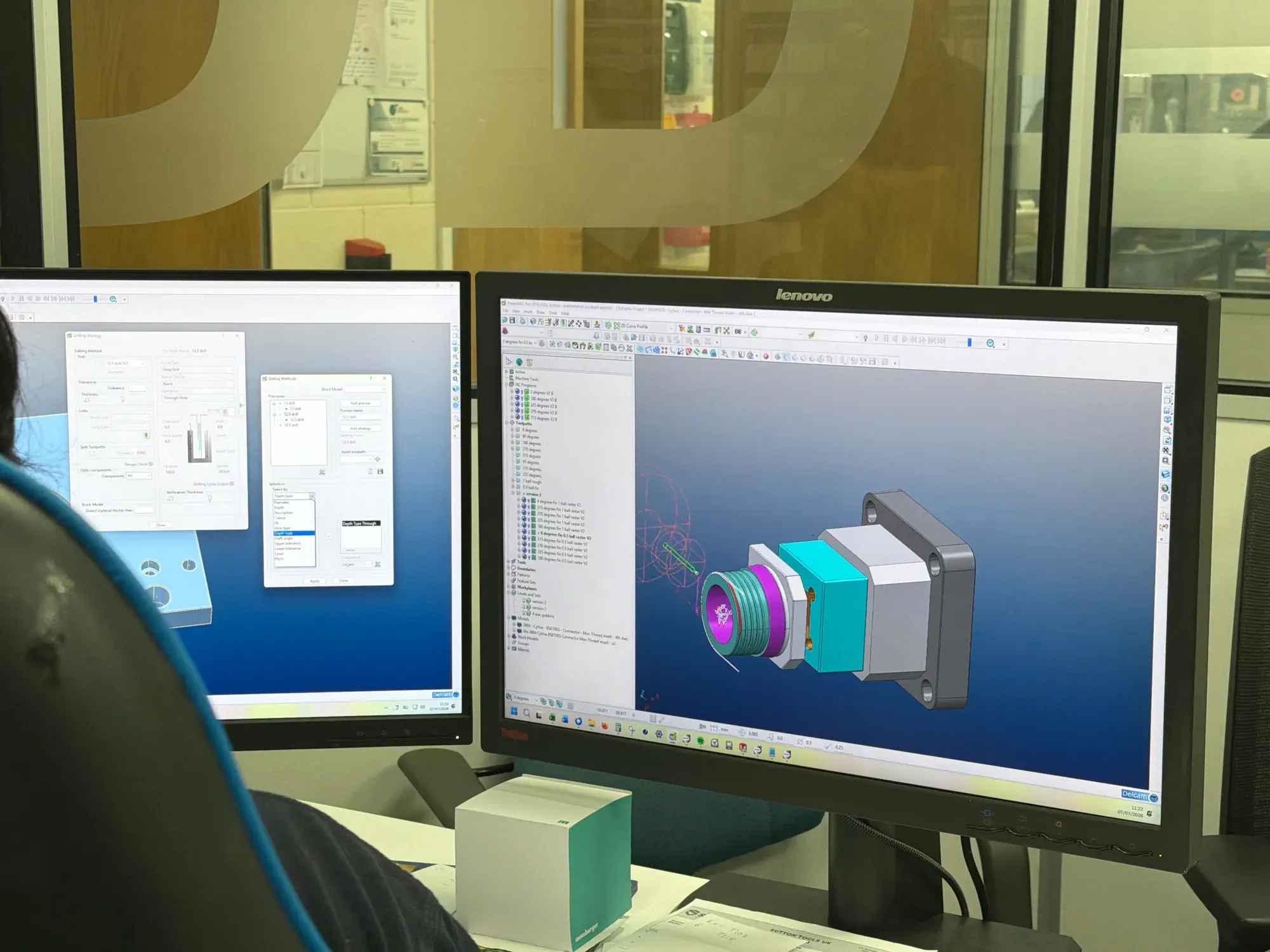
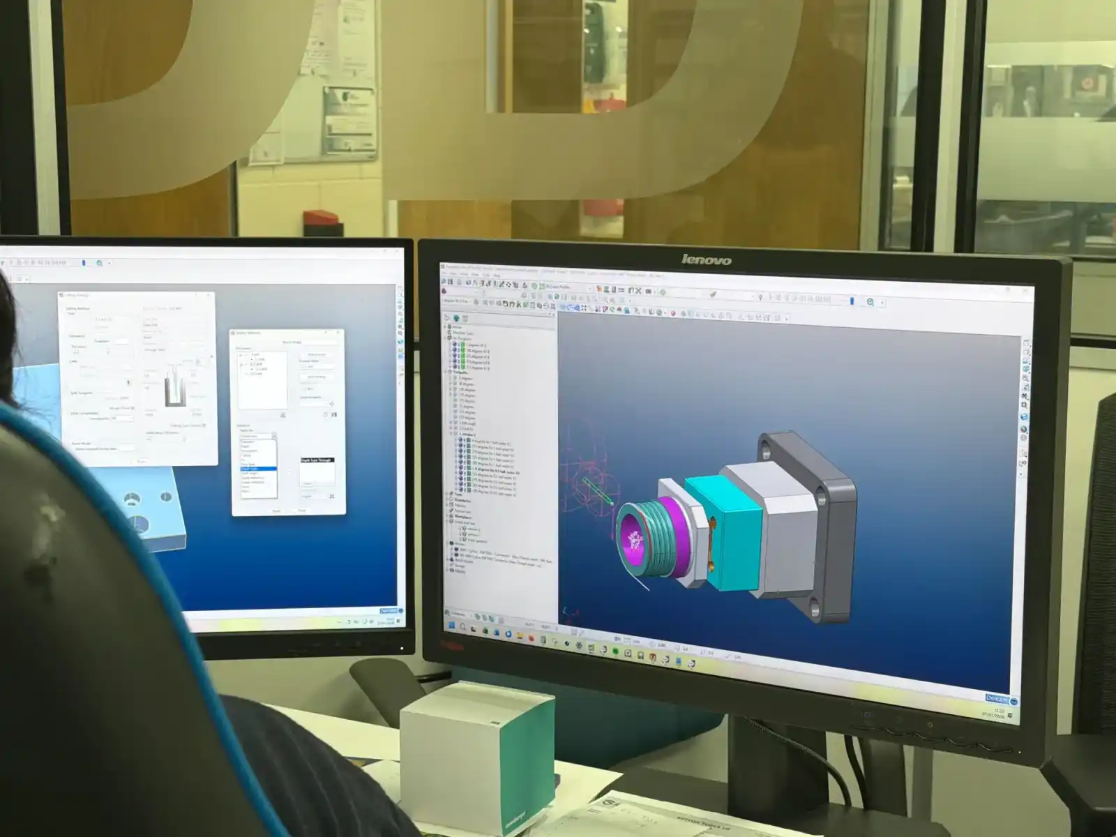
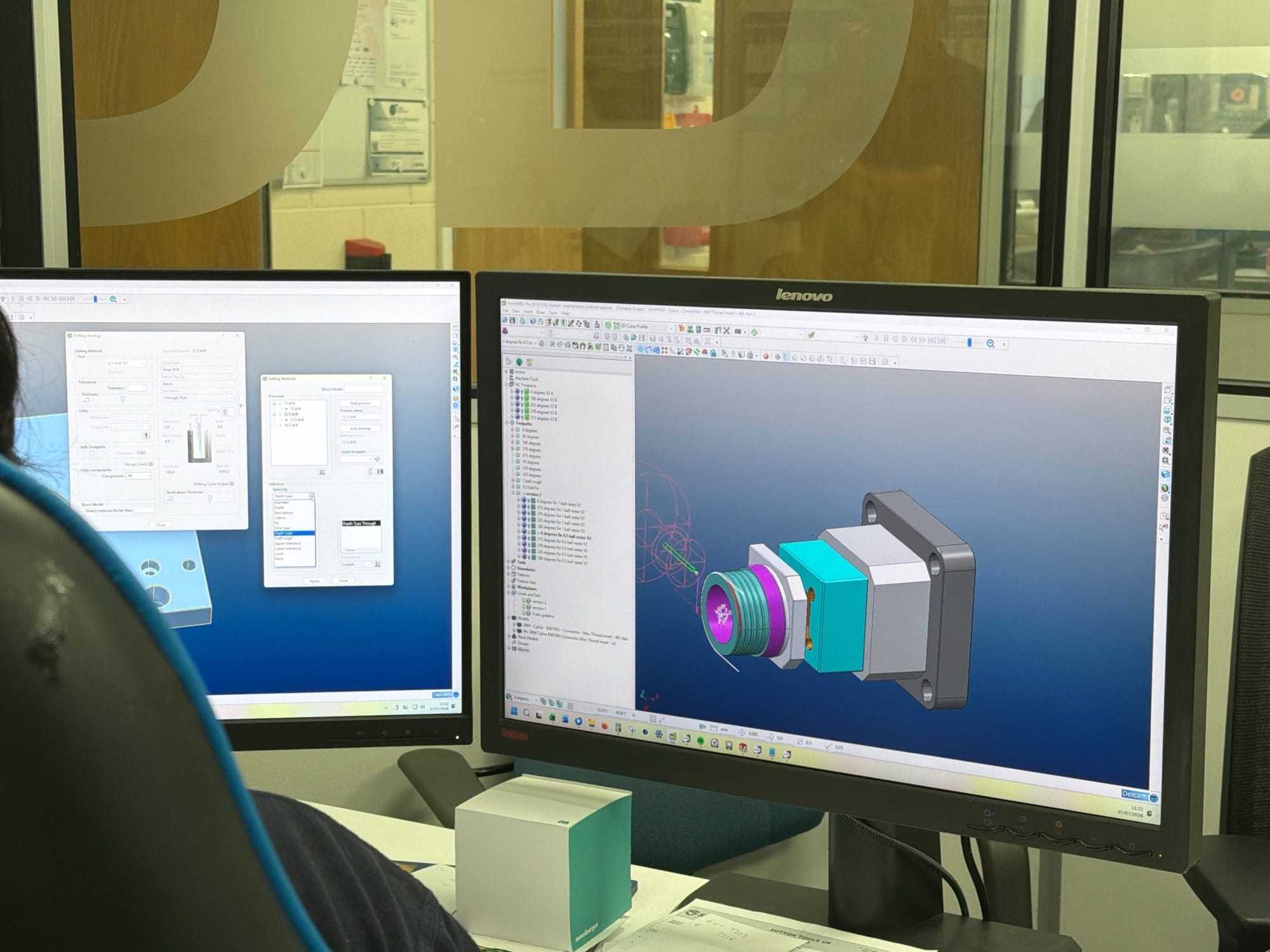
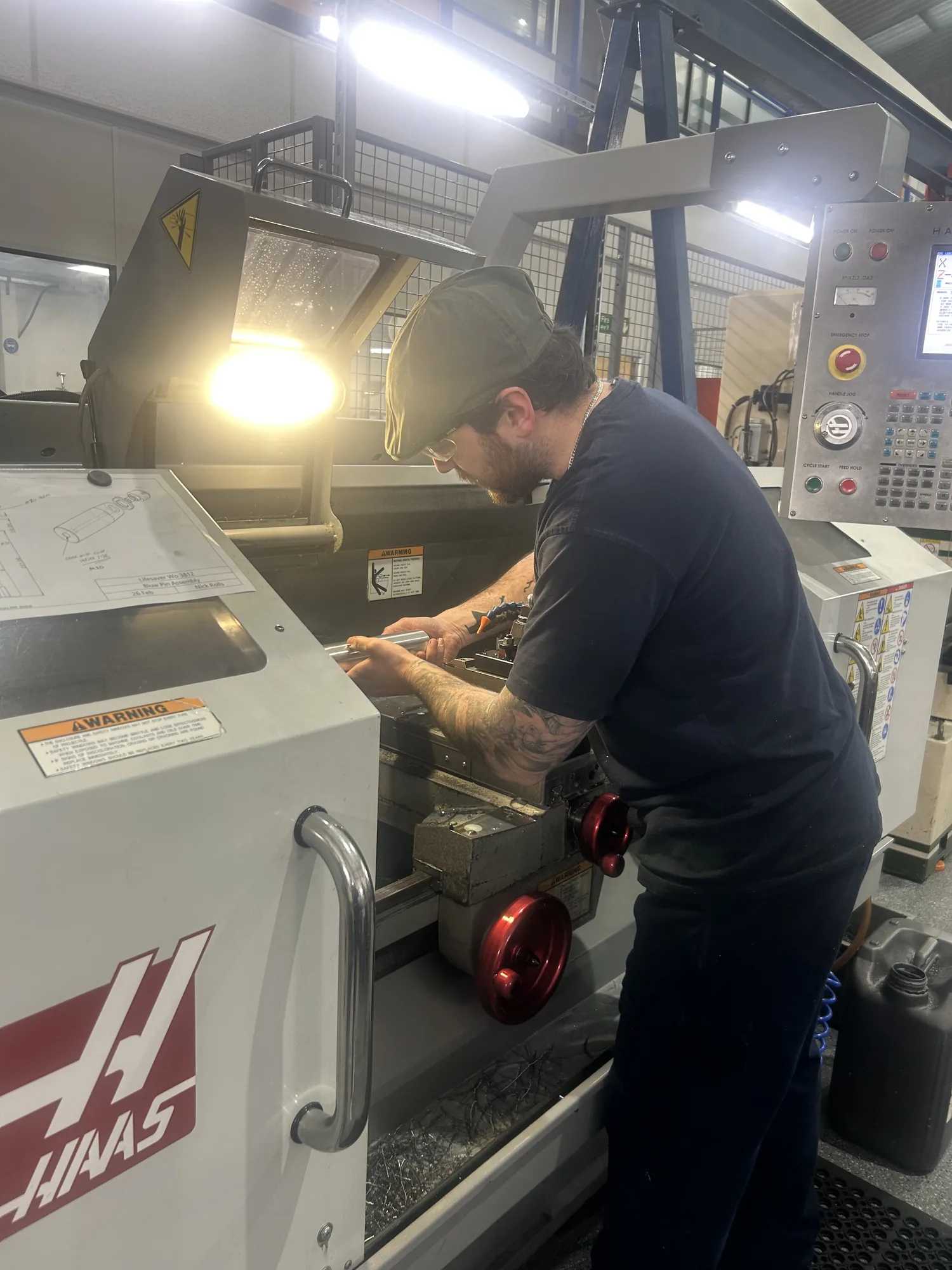
Our design for manufacture service shapes a plastic part around the tool and the moulding process before any work begins on the tool. The engineers who work on your design also cut the tool and mould the part, under one roof in the UK, so a part is designed to be made, not just drawn.
Design for manufacture looks at your part the way the toolmaker and the moulding press will see it. Decisions about undercuts, draft, wall thickness and gate position drive the cost and lead time of a mould tool, and they are cheapest to change while the part is still in CAD.
Because the same business designs the part, cuts the tool and moulds it, the work is done by the people who will make it. The aim is fewer surprises at production and, often, a lower part cost. You talk to the engineers doing the work, not a sales desk.
We work through the part's material, wall thickness, draft angles and parting line, the tooling risks and manufacturing concerns, and any chance to reduce cost, then suggest design changes. The checklist differs by process: injection moulding, blow moulding, stretch blow moulding and hot plate welding each have their own.
What We Check
What we check.
These are the decisions that most often add cost or time to a tool.
02 / What We Check
Wall thickness and cooling
Thick sections cool more slowly, and irregular wall sections can leave a part bent, twisted or covered in sink marks. Consistent walls cut those risks.
Draft and release
Faces that run in the direction of tool opening need draft so the part releases cleanly. Designed in early, it avoids costly tool modifications later.
Undercuts, slides and lifters
Side openings and clips can need slides or lifters, which add cost and moving parts to the tool. A small change to the geometry can sometimes remove them.
Parting line, gating and flow
Where the tool splits, where the plastic is fed in and how it flows through the cavity decide where flow marks and weld lines appear. Agreeing them before tooling prevents rework.
Material and shrinkage
Each polymer shrinks and flows differently, which sets cavity dimensions, gating and cooling. We advise on material before the tool is designed.
Flow and FEA analysis
Where a part needs it, we simulate the moulding process with flow and FEA analysis, and use B-Slim for blow moulded parts.
How It Works
From drawing to tool-ready design.
From your first drawing to a design ready for tooling, you deal with the engineers who will make the part.
01
Send your design
Send a STEP or IGES file, or a 2D drawing, with the material and volume you have in mind. A sketch or a sample works too.
02
We design it for manufacture
We work through draft, parting line, gating, material flow and wall thickness, and suggest changes. If you would like us to, we make them in CAD and send the part back for you to approve.
03
You get a fixed quote
We confirm tooling cost, part price and a fixed lead time before any work begins on the tool.
Design for manufacture is the practice of shaping a part around how it will be tooled and moulded. It means working through features such as wall thickness, draft, undercuts and gate position against the tool and the process, while changes are still cheap to make in CAD.
Is design for manufacture the same as design for manufacturing?
Yes. Design for manufacturing is the more common term in the US, and DFM is the abbreviation for both. They describe the same practice: designing a part around its tooling and production process.
When should design for manufacture happen?
Before any work begins on the tool, while changes are still cheap to make in CAD.
What do I need to send?
A STEP or IGES file is ideal, or a 2D drawing, with the material and volume you have in mind. If you only have a sketch or a concept, our in-house CAD team can take it from there.
Do you offer design for manufacture for blow moulding as well as injection moulding?
Yes, and the checks differ by process. For a blow moulded part we also look at the neck configuration, the punt design and the parting line, and we use B-Slim simulation software. We carry out design for manufacture for stretch blow moulding and hot plate welding too.
Will you change my design?
If you would like us to, we make the changes in CAD and send the part back for you to approve. A change such as adding a draft angle can alter a face that matters to how the part works, so you have the final say. If a face has to stay as it is, we design the tool around it instead, for example with a slider that pulls away from that face so the part can release.
Can you take on a tool made by another supplier?
Yes. We see it most often with blow moulding tools. Send us the tool CAD if you have it, or the tool's physical dimensions and a list of what you will send, such as the blow mould tool and blow pin. A design for manufacture assessment then establishes whether the tool fits our machines and what has to change, for example packing plates to raise the stack height or a new blow pin. We then quote for the tool conversion, and production is priced as normal.